| Version 12 (modified by , 5 months ago) ( diff ) |
|---|
Phase P2: Logical and Physical Design (DDL & DML)
Purpose and Scope of Phase P2
The objective of Phase P2 is to formally transform the conceptual ER model defined in Phase P1 into a logical and physical relational database design.
This transformation is required because an ER model is descriptive and conceptual, while a relational database requires a precise formal structure. Therefore, every conceptual element identified in Phase P1 must be translated into relational constructs that preserve its meaning and constraints.
All decisions in this phase are strictly derived from: 1) the ER model structure, 2) the cardinalities defined in Phase P1, 3) the real-world semantics of the wedding planning domain, and not from arbitrary or intuitive assumptions.
Basis for the ER-to-Relational Transformation
The transformation process follows established ER-to-relational mapping rules. These rules are necessary because relational databases do not support ER constructs directly.
The following principles were applied, each based on a specific limitation or requirement of the relational model:
- Principle 1: Strong entities must be mapped to separate tables. This follows from the definition of a strong entity, which has an independent existence and must therefore be stored independently in the database.
- Principle 2: Each entity must have a primary key. This requirement follows from entity integrity rules in relational theory, which state that each tuple must be uniquely identifiable.
- Principle 3: Relationships must be mapped according to their cardinality. Since relational databases represent relationships through references, the placement of foreign keys is determined by the cardinality of the relationship.
Mapping of Entities
Each entity identified in the ER model was mapped directly to a relational table. This decision is justified because each entity represents a real-world object with its own attributes and independent lifecycle.
For example: The entity User represents a real system user and therefore requires its own table. Its identifier (user_id) is mapped as the primary key to ensure uniqueness.
This reasoning applies equally to Wedding, Venue, Photographer, Band, Registrar, Event, Guest, and other entities.
Mapping of Relationships Based on Cardinality
One-to-Many (1:N) Relationships
In a one-to-many relationship, one instance of an entity can be associated with multiple instances of another entity.
According to relational mapping rules, such relationships are implemented by placing a foreign key in the table on the many-side of the relationship. This is necessary because the many-side depends on the existence of the one-side.
Example: A Wedding can have multiple Events, but each Event belongs to exactly one Wedding. Therefore, wedding_id is stored as a foreign key in the Event table. This directly enforces the cardinality defined in the ER model.
Many-to-Many (N:M) Relationships
Relational databases cannot represent N:M relationships directly. If such a relationship were implemented without an intermediate table, it would violate first normal form.
Therefore, every N:M relationship in the ER model was transformed into an associative table containing foreign keys referencing the participating entities.
Example: A Wedding can involve multiple Bands, and a Band can perform at multiple Weddings. This relationship was therefore transformed into the Band_Booking table, which references both Wedding and Band. The presence of additional attributes (date, time, status) further confirms that the relationship itself has properties and must be modeled as a separate entity.
One-to-One (1:1) Relationships
One-to-one relationships require special handling because both entities have equal cardinality.
In such cases, placing a UNIQUE foreign key in one of the participating tables is sufficient to preserve the relationship without redundancy.
Example: The ER model specifies a 1:1 relationship between Wedding and Church. This reflects the real-world rule that a wedding can be held in only one church, and a church instance in this context is associated with only one wedding.
This relationship is implemented by placing a UNIQUE wedding_id foreign key in the Church table. The UNIQUE constraint enforces the 1:1 cardinality explicitly at the database level.
Derivation of the Relational Schema
Based on the transformation rules described above, the following relational schema was derived.
Each relation corresponds either to:
- a strong entity, or
- an associative entity derived from an N:M relationship.
(User, Wedding, Church, Priest, Venue_Type, Venue, Venue_Booking, Photographer, Photographer_Booking, Band, Band_Booking, Registrar, Registrar_Booking, Event, Guest, Event_RSVP, Attendance)
No table exists without a direct conceptual origin in the ER model.
Data Integrity as a Consequence of the Model
Data integrity constraints were not added arbitrarily, but derived directly from the structure and semantics of the model.
Entity Integrity
Primary keys ensure that each entity instance is uniquely identifiable. Without primary keys, entities could not be referenced reliably, which would contradict the definition of an entity in the ER model.
Referential Integrity
Foreign key constraints ensure that relationships between entities remain valid. A record that references another entity cannot exist unless that entity exists.
For example: A booking without a corresponding wedding would have no real-world meaning. Therefore, foreign keys are mandatory to prevent invalid references.
Cascading actions are used to maintain consistency when parent records are updated or removed. This reflects the dependency relationships already present in the ER model.
Business Logic Constraints
Certain rules cannot be captured through keys alone. These rules are derived from real-world constraints and are enforced using CHECK and UNIQUE constraints.
Examples:
- Time constraints: An event or booking cannot end before it starts. This rule is enforced using CHECK (end_time > start_time), which directly reflects temporal logic in the real world.
- Domain constraints: Attributes such as price and capacity must be positive. Negative values would contradict the meaning of these attributes.
- Cardinality constraints: UNIQUE constraints enforce restrictions such as one church per wedding. This is a direct implementation of ER cardinality constraints.
These rules are enforced at the database level to ensure correctness independently of application logic.
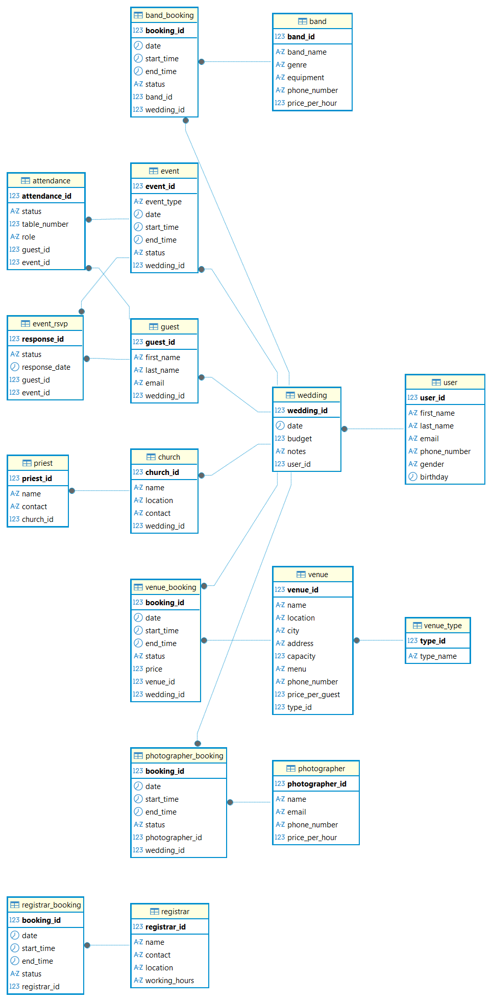
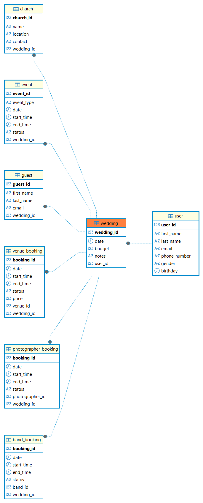
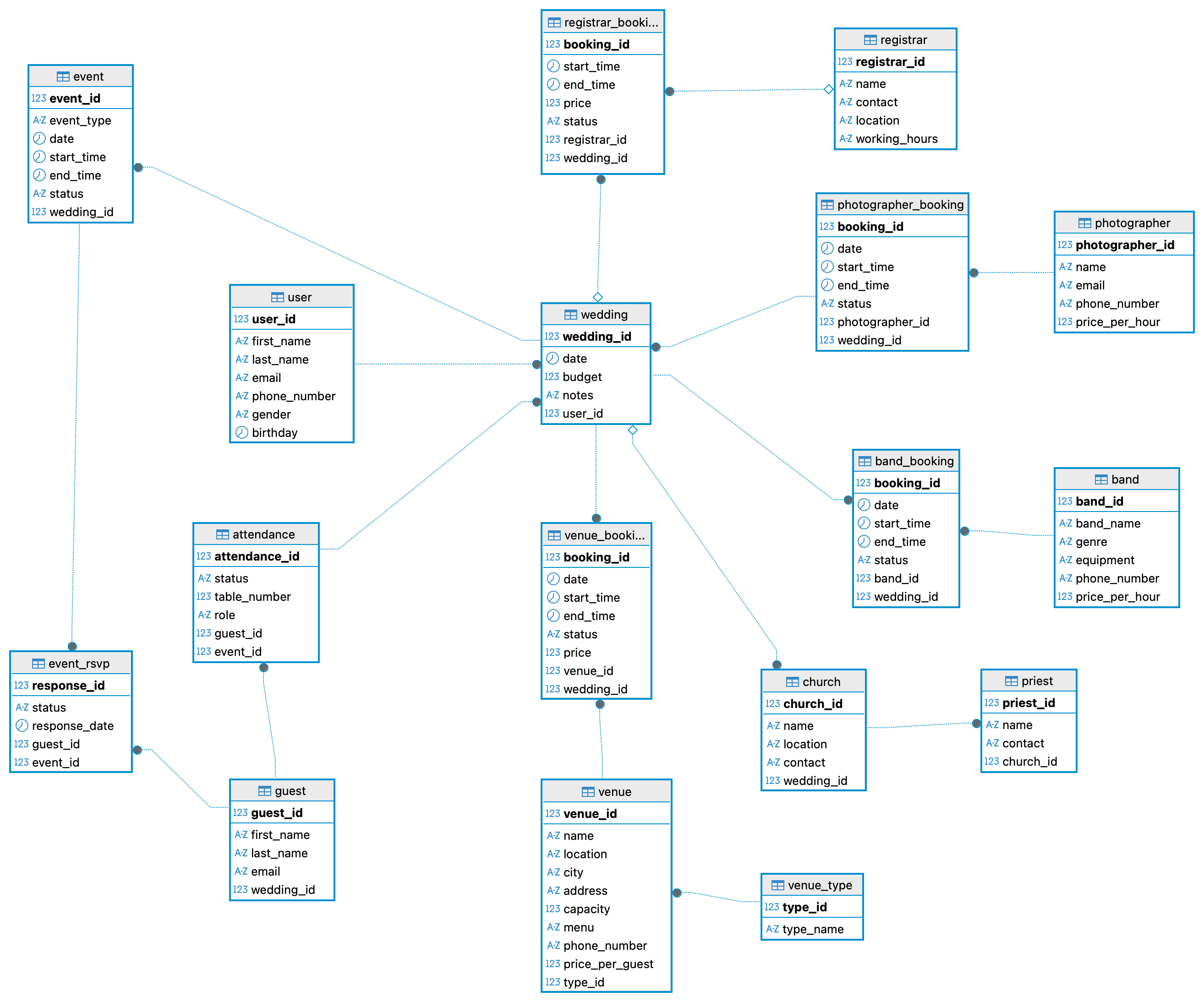
Relational Diagram
The relational diagram was generated directly from the implemented schema using DBeaver. Because the diagram is generated from the actual database objects, it serves as a formal verification of the relational model.
The diagram visually confirms:
- correct primary and foreign key placement,
- correct cardinalities,
- consistency with the relational schema derived from the ER model.

DDL and DML Implementation
The logical and physical design is implemented using two SQL scripts:
The DDL script defines the database structure and all integrity constraints. The DML script inserts sample data that complies with these constraints.
The successful execution of the DML script serves as additional evidence that the relational design correctly enforces the intended rules.
Attachments (6)
- data_load.sql (3.6 KB ) - added by 5 months ago.
- db_202526z_va_prj_wedding_planner v.2 - project.png (107.5 KB ) - added by 5 months ago.
- schema_creation.sql (9.0 KB ) - added by 4 months ago.
- final_version.png (60.7 KB ) - added by 4 months ago.
- wedding_planner_version_6_erd.erd (4.6 KB ) - added by 4 months ago.
- wedding_planner_version_6_erd.png (163.5 KB ) - added by 4 months ago.
Download all attachments as: .zip